Microphone Echo Circuit Diagram
This control should be adjusted so that the level indicated on the vu meter does not exceed +3 on voice peaks. Audio amplifier circuit components required.

ECHO REPEATER TL12201220A
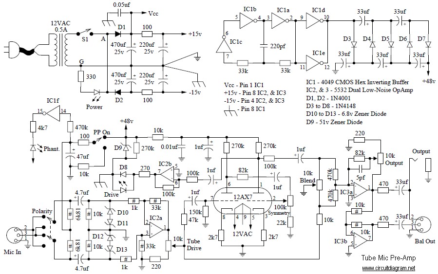
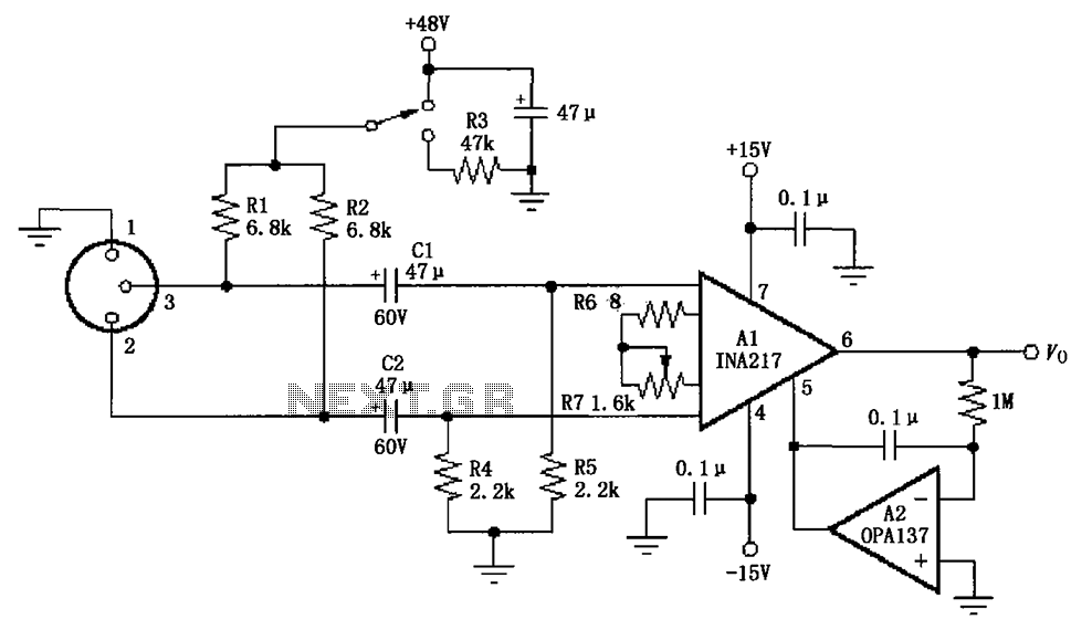
You can connect condenser mic with an amplifier circuit as given below diagram.

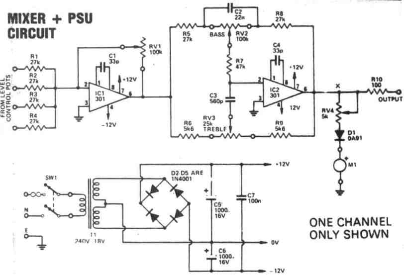
Microphone echo circuit diagram. 3 input mic mixer circuit. They produce a gain of around 40 decibel to the individual input signals. Pins labelled '1' are gnd.
The following design is the circuit diagram of microphone audio mixer with 3 input channels. So, i am planning to make my custom mic with opamp to amplify the sound signal. Echo dot gen 3 microphone disable circuitry colin o flynn.
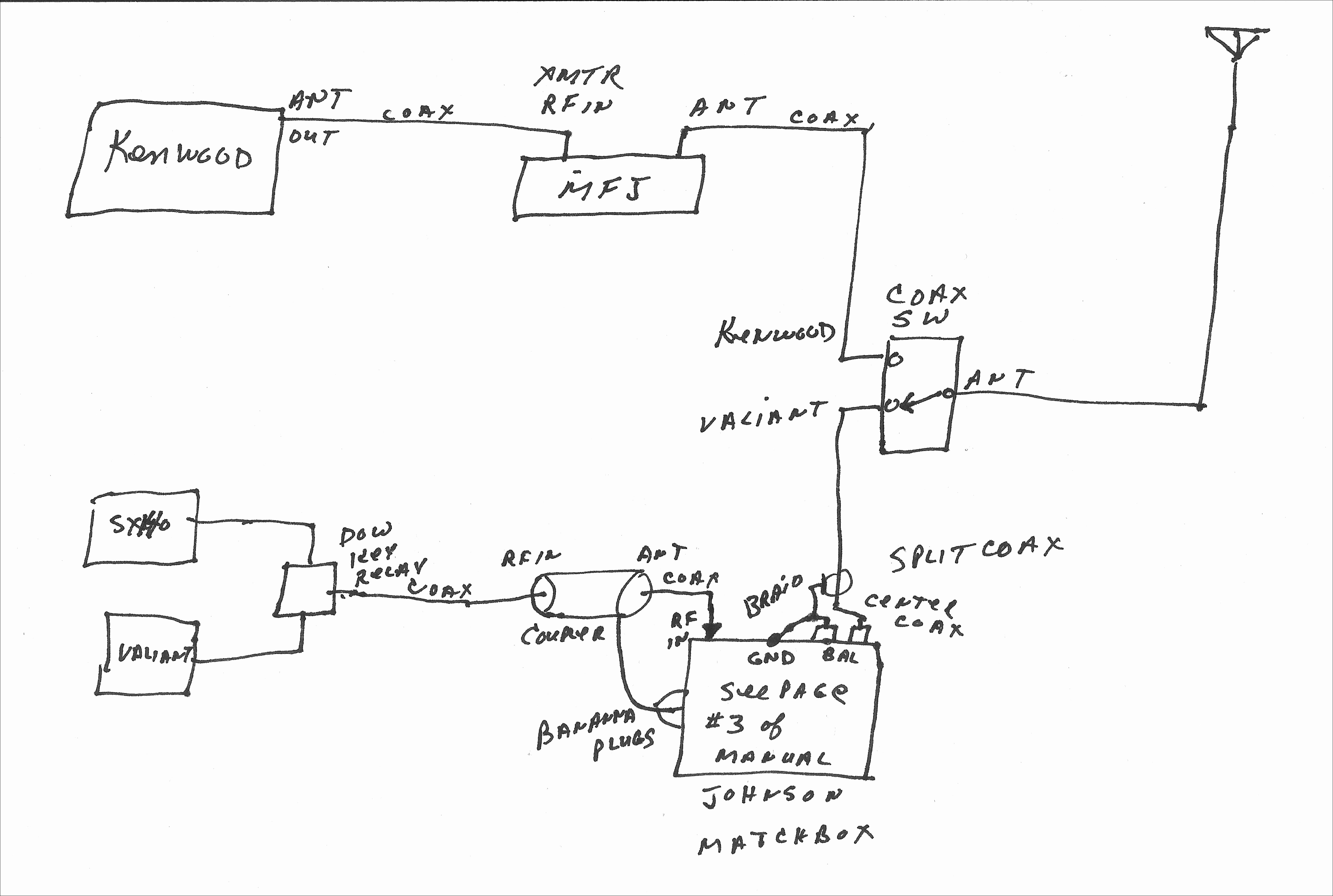
By using a digital echo circuit ic designed especially for the heart to work. The main wiring is the same a fig. (i was assuming gnd, vcc, analog out kind of stuff so that i could replace the mic with the red modules shown in the bottom left part.
This is the wiring of the mic (which confused me actually): Speak to microphone and the modulation (modul) level. We removed the 10k pot section and added additional bias circuitry of the microphone amplifier.
Resistors 1k, and 100k 1/4 watt capacitors (10uf) transistors any small signal type such bc547 or 2n3053 condenser mic speaker (8ω, ½ watt) working of amplifier. Connect the microphone to the transceiver following the wiring norms enclosed. We will continue to try to get all the information that we can listed on this page.
The list below offers some microphone wiring information. The chart and image above are correct for these models: This one was manufactured in the 90's by sadelta of spain and is still in production and to buy under the name of galaxy echo master plus classic (quite rare for an almost 30 years old electronic device).
Battery housing so oe oe below side 3. Condenser mic, audio amplifier and loudspeaker. Microphone mixer circuit 3 input mic 4 simple audio circuits diagram channel low cost using operational amplifier 5 explained how to build an preamps mixing console part 1 pre searching projects category schematic preamplifier portable page three red page53 digital echo stereo compact dj station page140 engineering mini line for pc single.
In the circuit diagram, the amplifier is shown with the respective pin diagrams. Mic wiring can be frustrating enough, but when you can't find the right wiring info, it is just impossible. However 2 and 3 tend to produce similar output.
The echo chamber circuit is great for human voice (karaoke), i doesn't needed for music sound. The dual tone roger deep is automatically activated when releasing the ptt button. 4 input microphone audio mixer all about circuits.
Here is a simple 3 input mic mixer circuit using the popular ua 741 ics. This circuit will work very well with any type of audio amplifier. The setting of this control will vary depending on how far away.
Connect the positive terminal of the mic with 10 k resistor in series with the positive supply and the negative. Four 741s are used here.ic1, ic2, ic3 are used as preamplifiers. Insert the battery (see fig.).
Be seen from the circuit, is quite simple consists of the main equipment are 4 transistor and 5 ics only. Laptop audio out splitter circuit diagram. Below circuit is an echo chamber circuit which can be used for smoothing your voice from the microphone.
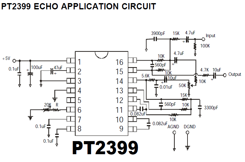
Usually this set is used to switch voltages from receiver to transmitter. Pt2399 basic echo circuit simple voice electronics lab com digital stereo mixer projects effect with ic 4558 preamp board for microphone mic pre amp based lm358 audio circuits dc 12v sound mfos rockit producer processor 3 input multiple controls diagram hobby under repository changer dot gen repeter. (b), but there is another set of wires d, e, f.
Mic gain the mic gain slider control sets the level of signal into the digital circuitry. This circuit may used for any kind of audio signal (microphone, radio, mp3 player, etc). How to make sound delay circuithi friend in this video i have made a sound delay circuit which produces echos in the sound i hope you enjoy this video please.
The circuit is exactly same as shown in the lm386 datasheet from texas instruments. Astatic communication microphones wiring diagrams and more!! The sadelta echo master plus classic is an electret base station microphone with amplifier, and echo.
Voltage is on wire e, then e, d will supply voltage to receiver. The two transistor mic amplifier circuit is isolated into three sections:
Mic Mixer With Echo Schematic Diagram MRSKELLYWALTER6969
Echo Repeter and preamp mic schematic Electronic Circuit

Mic Mixer With Echo Schematic Diagram Circuit Diagram Images
Microphone Echo Circuit Diagram Galaxy Radios DX22B

Voice echo schematic
Echo Mic Circuit Diagram Micpreamp Main Wiki / This
Basic Electronic Circuit Design Diy Electronic Circuit

Wiring Machine Microphone Echo Circuit Diagram

Wiring Machine Microphone Echo Circuit Diagram
Draw your wiring Mic Mixer With Echo Schematic Diagram

Mic Mixer With Echo Schematic Diagram Circuit Diagram Images


Mic Mixer With Echo Schematic Diagram Circuit Diagram Images
Echo Wiring Diagram Wiring Diagram

Digital Echo Circuit PT2399 Electronic Circuit

Mic Mixer With Echo Schematic Diagram Circuit Diagram Images
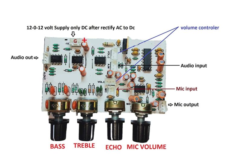
PreMic Circuit Board with Echo, Bass, Treble, Delay

Pin on Electronic Project Ideas

Mic Echo Circuit Diagram 1 Bass treble circuit diagram

HiFi Microphone Preamplifier circuit schematic